
LiftMaster CSW24UL Manuals & Support

Identify your model
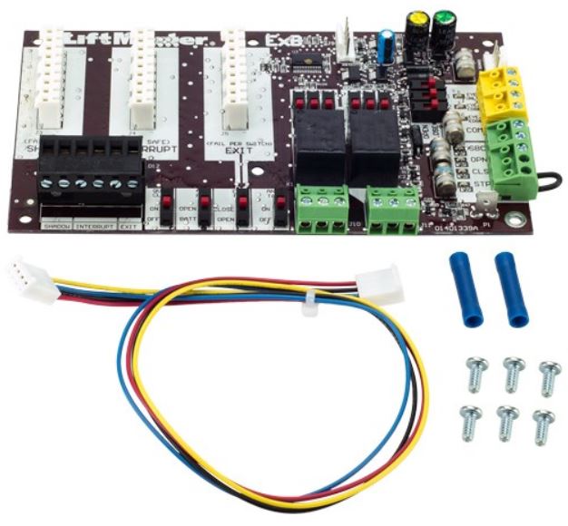
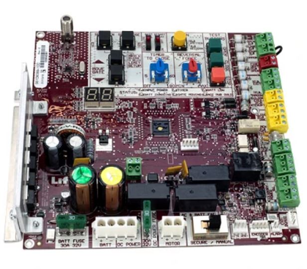
The model number is on the label inside the cover. A CSW24UL has a main control board (K1D8389-1CC), an expansion board (K1D8387-1CC), a Security+ 2.0 receiver and an LED diagnostic display.
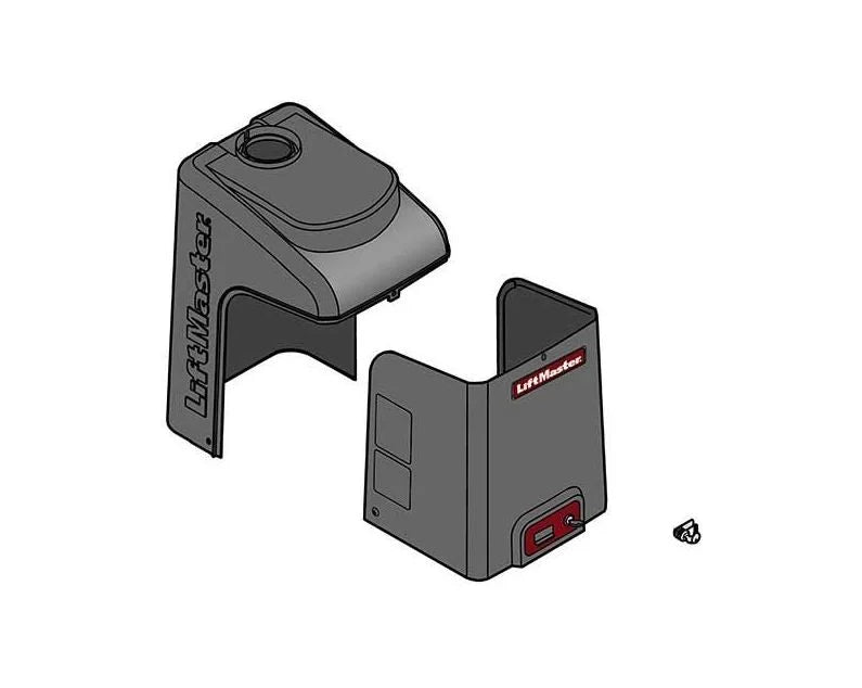
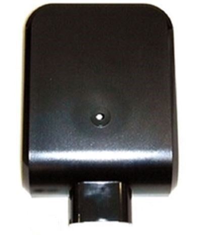
Older CSW24U and CSW24V operators use different control boards and some different covers. Check the model number on the label before you order boards, covers or harnesses.
Key specs
| UL 325 usage class | Class I, II, III and IV |
|---|---|
| Main power | 115 VAC, 4 A (10 A with accessory outlets) or 240 VAC, 2 A |
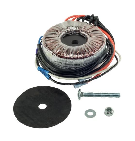
| Other input voltages | 208/240/480/575 VAC, 1-phase, with the 3PHCONV transformer kit |
| Operating voltage | 24 VDC, transformer run with battery backup |
| Max gate | 1,600 lb up to 8 ft; 800 lb at 16 ft; 600 lb at 18 ft |
| 90 degree travel time | About 20 seconds, depending on mounting |
| Max travel | 115 degrees |
| Duty cycle | Continuous |
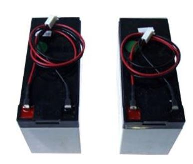
| Batteries | Two 12 V, 7 Ah included; two 33 Ah optional |
| Battery standby | Up to 146 cycles or 24 days on 7 Ah batteries |
| Accessory power | 24 VDC, 500 mA max |
| Solar | 24 VDC, 60 W max |
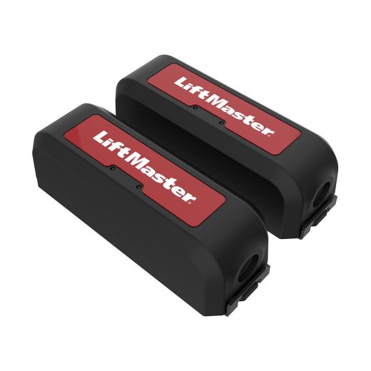
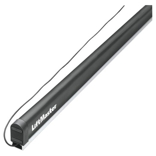
| Entrapment inputs | Main board: 2 close and 1 open. Expansion board: 3 more, plus up to 4 wireless edges with LMWEKITU |
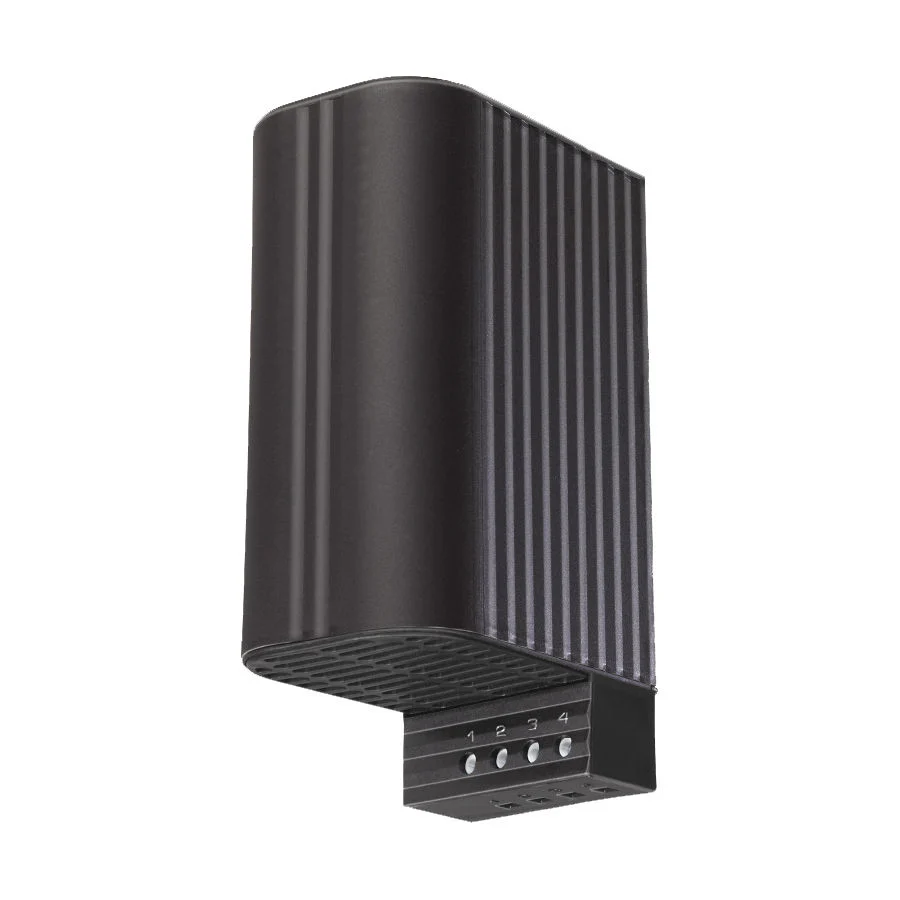
| Operating temperature | -4 to 140 °F; down to -40 °F with the HTR heater |
| Operator weight | 206 lb |
Manuals and documents
Installation Manual
-
CSW24UL Installation Manual
View PDF: CSW24UL Installation Manual (opens in a new tab)
Wiring Diagram
-
CSW24UL Wiring Diagram
View PDF: CSW24UL Wiring Diagram (opens in a new tab)
Spec Sheet
-
CSW24UL Data Sheet
View PDF: CSW24UL Data Sheet (opens in a new tab) -
CSW24UL Dimension Drawing
View PDF: CSW24UL Dimension Drawing (opens in a new tab)
Brochure
-
CSW24UL Product Guide
View PDF: CSW24UL Product Guide (opens in a new tab)
Other documents
-
CSW24UL Architectural Specification, Section 32 31 00 (Word)
Download file: CSW24UL Architectural Specification, Section 32 31 00 (Word) (opens in a new tab)
Troubleshooting
Common questions
Check for an active Open input or exit loop, the Timer-to-Close setting and the Fire Dept input. With AC power out, the AC FAIL or LOW BATT switch set to OPEN will hold the gate open. A blocked close photo eye or edge also stops the close.
It uses two 12 V, 7 Ah batteries. Replace them about every 3 years. You can upgrade to two 33 Ah batteries with the K94-37236 solar harness kit and a second battery tray. Do not mix 7 Ah and 33 Ah batteries, and 33 Ah batteries will not fit with the heater installed.
The alarm sounds after two obstructions in a row. Remove the obstruction, then press the reset button. Normal operation resumes after the reset.
Press the reset switch to RESET/DISCONNECT, then release the handle on the operator arm. On a dual gate, release both arms. Push the handle back down to lock the arm again.
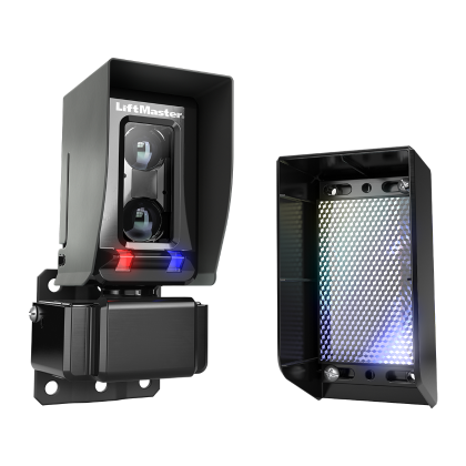
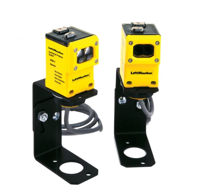
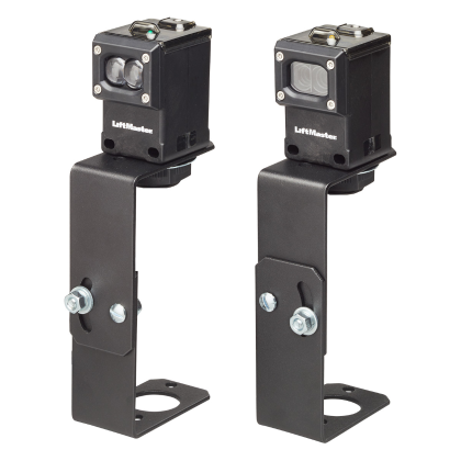
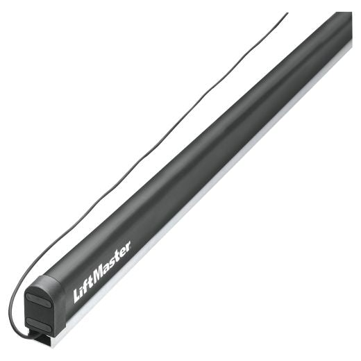
Yes. The operator needs at least one external monitored entrapment device before it will run. It comes with an LMRRUL photo eye. Use LiftMaster monitored devices to cover every entrapment zone in both directions.
Replacement parts
Parts diagram: LiftMaster CSW24UL Parts Diagram and Replacement Parts