
Linear SLC Manuals & Support

Identify your model
The model number is on the label inside the cover, for example SLC-121. The first digit after the dash is horsepower, the second is voltage and the third is phase.
- Horsepower: 2 = 1/2 HP, 1 = 1 HP
- Voltage: 1 = 115 VAC, 2 = 208/230 VAC, 4 = 460 VAC, 8 = 208 VAC
- Phase: 1 = single phase, 3 = three phase
Have the model and serial number ready when you order boards or motors. Parts can differ between single and three phase units.
The SLR is the residential version and the SLD is the 24 VDC battery backup version. All three share one manual.
Key specs
| Horsepower | 1/2 or 1 HP |
|---|---|
| Max gate | 1,000 lb / 37 ft (1/2 HP); 2,000 lb / 45 ft (1 HP) |
| Gate speed | About 11 in per second |
| Duty cycle | Continuous |
| Power | 115 VAC or 208/230 VAC single phase |
| Drive | Size 60, 20:1 reducer; #41 chain (1/2 HP) or #40 chain (1 HP), 31 ft included |
| Controller | APeX with MegaCode receiver, LED display, 0 to 9 minute auto close |
| Mounting | Pad mount standard; post mount with kit 2120-483 |
| Accessory power | Regulated 24 VDC |
Manuals and documents
Installation Manual
-
SLR, SLC and SLD Installation Guide (APeX)
View PDF: SLR, SLC and SLD Installation Guide (APeX) (opens in a new tab) -
SL Series Mounting Pad Installation
View PDF: SL Series Mounting Pad Installation (opens in a new tab) -
SWC and SLC Post Mount Kit
View PDF: SWC and SLC Post Mount Kit (opens in a new tab)
Wiring Diagram
-
SL Series Wiring Specifications
View PDF: SL Series Wiring Specifications (opens in a new tab)
Spec Sheet
-
SL Series Spec Sheet
View PDF: SL Series Spec Sheet (opens in a new tab)
Other documents
-
Typical Slide Gate Loop Layout (3 Loops)
View PDF: Typical Slide Gate Loop Layout (3 Loops) (opens in a new tab)
Troubleshooting
Common questions
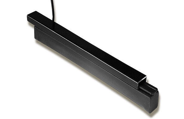
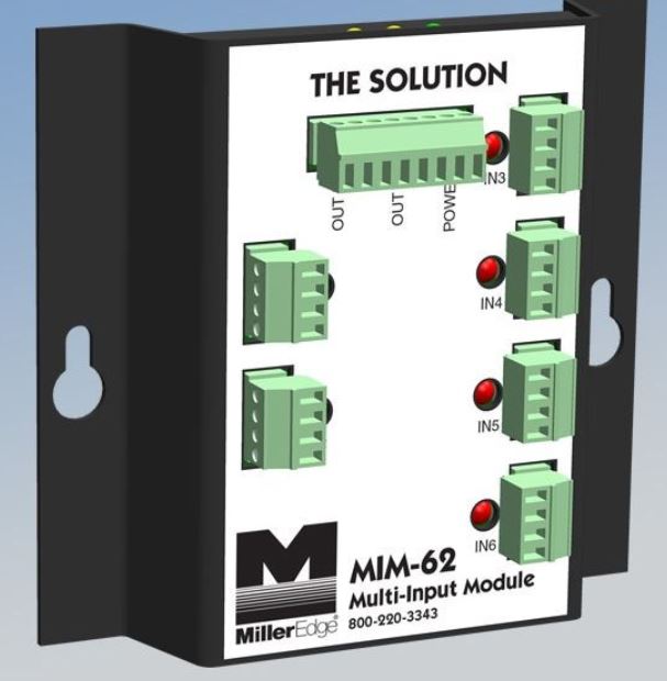
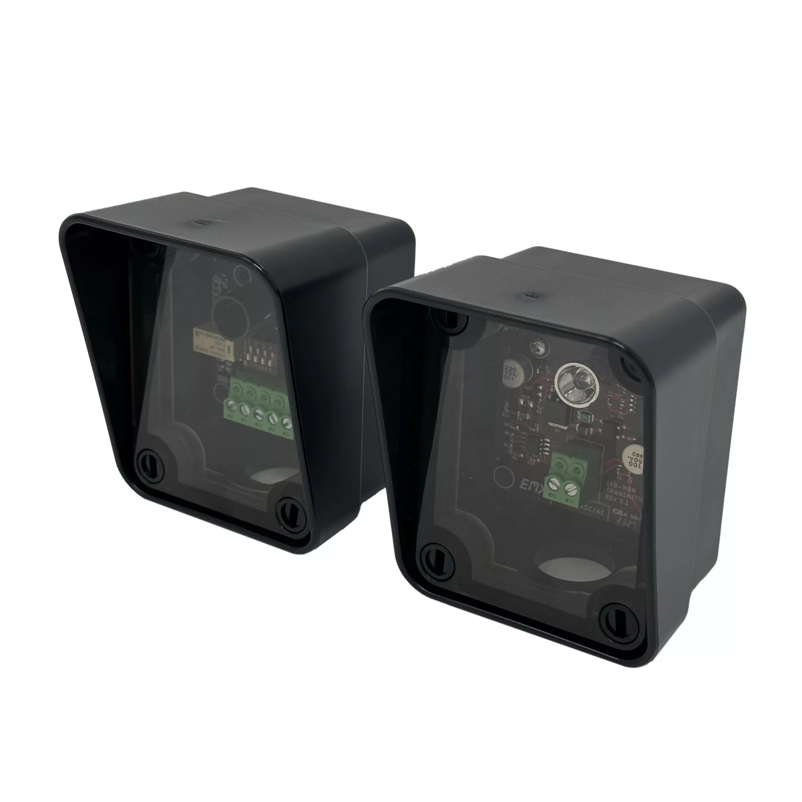
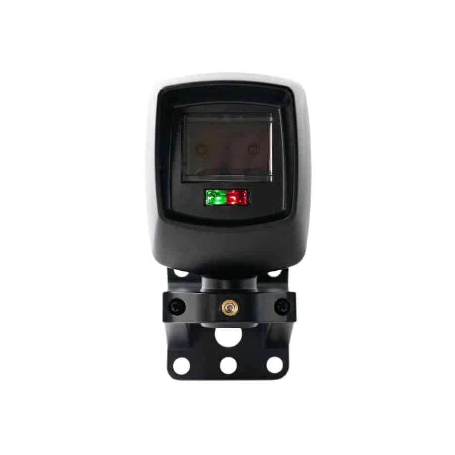
It needs at least two monitored safety devices, one for each direction of travel, before it will run. Approved devices include Miller Edge MGO20, MGR20 and MGS20 edges, the Miller Edge MIM-62 module, Omron E3K-R10K4-NR, Miller Edge RG-K-R and PG-K-R50 photo eyes, and EMX IRB-MON and IRB-RET photo eyes.
Two obstructions in a row lock the operator out and the beeper sounds. Clear the obstruction, then press STOP or the RESET button on the cover.
The max run timer ran out while opening (En 01) or closing (En 02). Look for a broken chain or belt or a slipping sprocket, and check the timer setting. Press STOP to clear it.
Connect the COMM LINK terminals A, B and C on both operators with 3-wire shielded cable (Belden 8760, Linear P/N 2500-1982). Set limits and entrapment settings on each operator alone first, then set both to dual gate.
Yes. Pad mount is standard. Use the optional 2120-483 post mount kit for a post.
Replacement parts
Parts diagram: Linear SLC Parts Diagram and Replacement Parts